
Mikroelektronika easyAVR6
Alright, today we're having a look at the EasyAVR6, a development board for Atmel AVR 8-bit DIP microcontrollers.
Atmel is one of the largest companies who manufacturers microprocessors for hobbyists and professionals. Their range of products goes from 8-bit AVR up to 32-bit ARM units with speeds from a few megahertz to a gigahertz and beyond.
The simpler processors, like the AVR series, features just a few simple but still very powerful functions which makes it possible to create products such as mp3-players, web servers, robots and pretty much anything you can think of.
For example, to build a simple HTML based web server you only need an AVR running on just a few megahertz and a really small flash memory like 8 kilobytes. With this web server you can either control servos, relays for lamps or other electrical equipment, read sensors like temperature or humidity, the possibilities are endless.
Just to mention before we head on, another company that should be mentioned are Microchip who also manufactures RISC processors who's name are PIC. They also produce several different other products as well, such as ENC28J60 which is a popular Ethernet en/decoder used in both PIC and AVR projects.
The fun thing is that with some code, similar (but not exact copy) between the two families, you can make PIC processors communicate with an AVR processor and vice versa. As well as make PIC communicate with other PICs and AVRs with other AVRs of course.
Well that was just a short introduction to the processors, but now it's time to take a look at the EasyAVR6 from mikroElektronika.
EasyAVR6 comes in a green and silvery box with mikroElektronika's logo in large print on it. We also see a circuit image on the front that looks like some drunk have drawn, I don't know if that circuit works, but it does look stylish on the package ;)
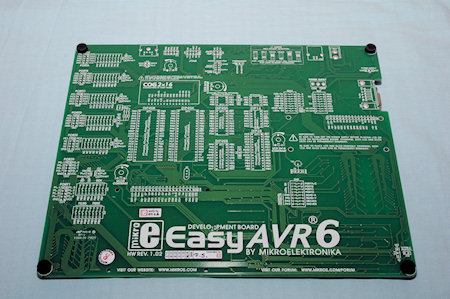
Inside we find the development board itself, it was delivered in an anti-static bag but I have removed it before the photo was taken. A quick look on the backside reveals that pretty much all the pins connected are documented, so if you ever need to do something on the backside you will know where to look. Great feature!
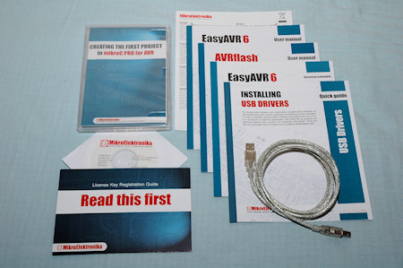
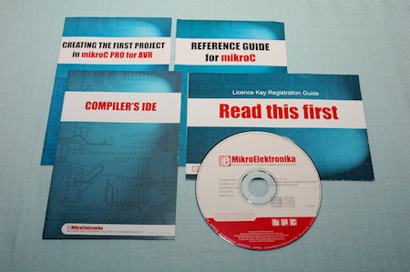
We also find some accessories such as USB cable and manuals. Together with our box we also got mikroC Pro test it out with the board. The software itself will get a separate review in the near future.
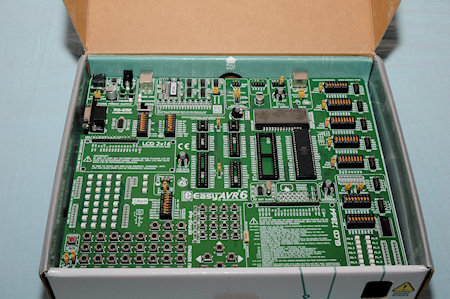
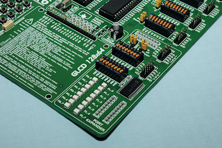
It is quite a large board with buttons, sockets and dip-switches all over it. We also find LEDs, headers and one onboard display and two headers for an additional two LCD displays, Liquid Crystal Display.
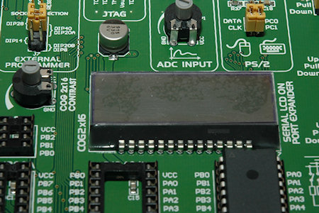
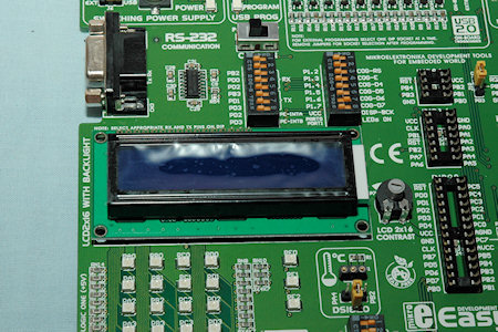
The onboard display is of the type COG, Chip-On-Glass. This kind of display does not offer a lot of features but it is slim and does its job very well. It is also nice to see that we get one onboard display right out of the package. This display can be connected to your AVR device through the onboard port expander that we will talk about more later.
The other two displays you can connect are one character LCD display with a maximum of 2 lines and 16 characters. Well at least if we should follow the silkscreen and the manual, but we could probably use for example 4x16 and 4x20 as well.
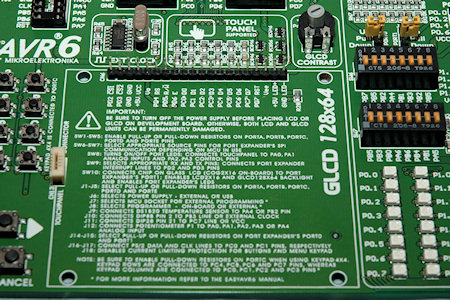
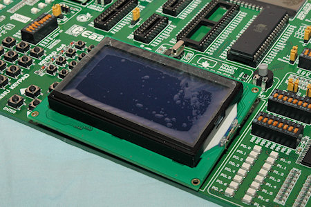
We also find a space for a GLCD, which stands for Graphical LCD, with a total size of 128 by 64 pixels.
For each of the displays we have a contrast potentiometer where you can adjust the contrast independently.
One thing to watch out for, when you want to connect a LCD or GLCD display make sure that the pinout on the display corresponds to the silkscreen on the EasyAVR6. If they don't match, bad things may happen.
But don't worry, you can connect pretty much any display as long as you take care of the connections, either by disassembling a cable or by making a converter board.
The GLCD can also be equipped by a touchscreen film and directly connected to the EasyAVR6 through an onboard connector.
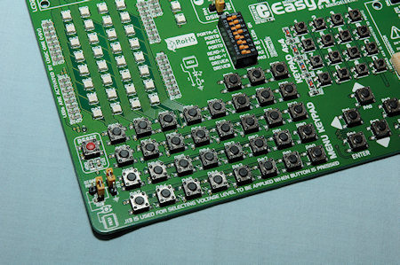
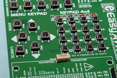
Moreover we find the LED and button departments, where we have a total of 32 LEDs and 32 general IO buttons. But that is not all, even if they are connected to the same IO bus as some of the general buttons, we have 22 additional buttons arranged in both a numerical keypad design and a menu navigational keypad.
This is however the grand maximum and some AVR processors supply a lot less than for example the ATmega16 or ATmega32 which have A, B, C and D IO ports.
Just to the left of the buttons we find the master reset button, colored in red to make it stand out among the other buttons. We also find two jumpers where we can both configure a pull-up or a pull-down mode as well as override and connect the buttons directly to VCC or ground.
On the right side of the LEDs we also find a configure switch where you both can turn on/off the LEDs but also configure the touchscreen controller connection to your AVR.
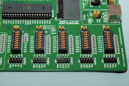
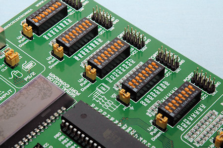
More on the IO pins, Input-Output pins, if we take a look at the rightmost part of the board we find headers for up to all five IO ports on the AVR.
These can be configured in a similar manner to the buttons, with pull-up or pull-down resistors. Only here you can configure every pin individually, which makes up for a much greater control over your IO pins. Other than that the headers are standard 10 pin with both VCC and ground connections available.
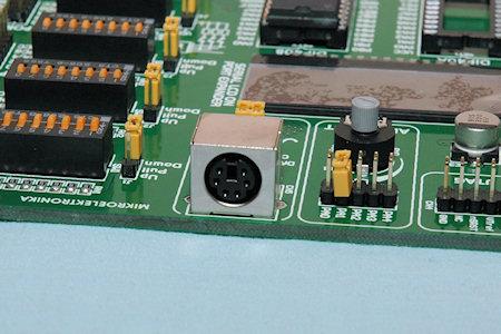
Other IO connectors are the PS/2 PC keyboard/mouse connector, which can be enabled on PortC pin 0 and 1. In the picture PortC 0 and 1 is not connected, it's just the angle.
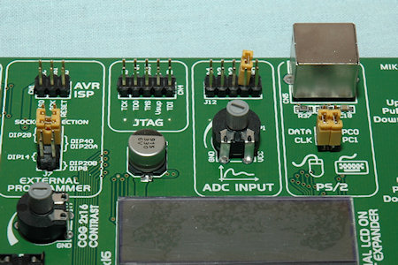
To the left we find an onboard ADC, analogue to digital converter, input which has a potentiometer already installed to it. With a 10 pin header you can then choose if you either want it connected at all or which ADC port you would like to connect it to.
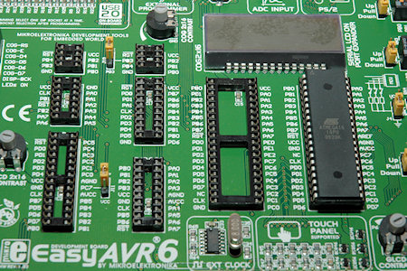
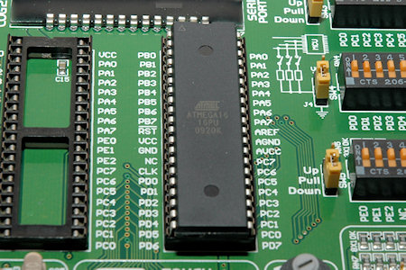
More to the left we find the JTAG and ISP headers for debugging and connecting an external programmer to the board. We can also choose which MCU DIP socket to be active as you can't have more than one AVR onboard at once.
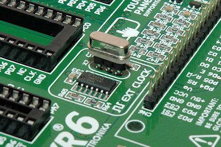
As you can see in the picture above, we have a few sockets to choose from. All down to 8 pin up to 40 pin and with the board we got an ATmega16 already installed. Most AVR comes with a built-in crystal but for some projects you either choose an AVR without a built-in crystal or need to use an external for other frequencies.
Then you can change the crystal in the socket that is just below the MCU sockets. Together with the board we get an 8.000 MHz crystal.
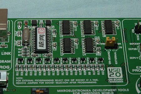
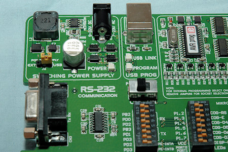
Continuing to the left we find the AVR Prog onboard USB programmer and the accompanying USB port to be able to program the MCU from a computer with a USB cable.
One thing to notice here, is that you can either use one of MikroElektronikas software programmers, such as the mikroC, microBasic or the microPascal, but you can also use any other programming software and use the hex file with AVRProg2 that comes with the easyAVR6 and program it that way.
Ok, that way you won't have a "one program" solution, but you can get the best of different worlds this way.
Just below the programmer circuit we can also find the power switch.
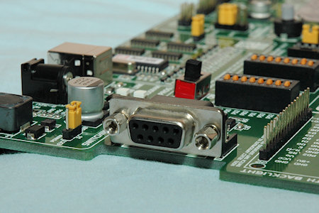
We also find the power supply input which can take from 7 Volt up to 23 Volts AC or 9 Volt up to 32 Volts DC. We can also choose if we would like to use the power jack with a wall wart or to use the power from the USB connector.
Below that we can find the RS-232 connector and together with the configuration switch to the right of that port we can both turn on or off the RS-232 connector and decide to which port pins the connector should be connected. This of course depends on which AVR you use, so you need to match the correct settings here.
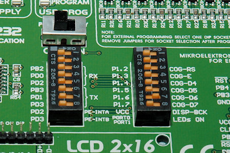
One thing we haven't talked about yet is the port expander down the right corner of the board. This port expander is both used for the COG display if you configure the board to enable that display, but also as two extra ports if you need it.
Here you can also configure pull-up and pull-down as well as override the setting if you would like. We can also use a total of 16 extra LEDs for IO pin status or just for fun if you feel for that ;)
The last thing I have to talk about is the DS1820 header. Except the LCD headers and the COG display this is probably the most "fun" part included on the easyAVR6 board.
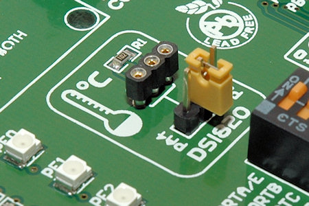
For those of you who asks "what the melon is DS1820", I'll explain that. DS1820 with different similar versions is a temperature sensor that operates on the 1-wire interface. Ok so what does that mean?
Well, this means that a 1-wire product has at least three pins that are crucial. VCC, GND and the Data pin. From the data pin you can, in example with DS1820, read the temperature in some way.
That's great, but what's even more great is that 1-wire devices also has unique serial numbers which mean you can connect several both the same kind of components as well as other kind of sensors, memories and such.
For example, you can connect 5 temperature probes on the same data line, but you can also add an eeprom memory component to the same bus. Together with serial numbers or for the eeprom, a configured address by configuration pins, you can control and read the different devices as if they were connected alone to different IO pins.
Anyhow, running away from the topic a bit here, but we have an DS1820 header onboard so all you need to do is connect one DS1820 sensor and then either write some code or use the accompanying example with one of the programmers, microC / microBasic / microPascal, to read the sensor details.
All in all, this is a large development and testing board with lots of features such as headers and dip-switch configurators. LCD/GLCD support with also an onboard COG display together with LEDs and buttons make this a great first-try for any newcomer to the AVR scene.
As well as those who need a new fun board for developing new circuits.
So, after this, is this all? Well not really, MikroElektronika has made sure we've just only started. On next page we'll take a look at some expansion modules that you can get for your board.

Christopher Fredriksson






![[H]ard|OCP, https://www.hardocp.com](https://swemod.com/uploaded/affiliates/hardocp.jpg)
![[M]adshrimps, https://www.madshrimps.be](https://swemod.com/uploaded/affiliates/madshrimps.jpg)
